
Voltage, Current and Resistance for Alarm Systems
- Voltage, Current and Resistance for Alarm Systems
- What Is Voltage?
- What Is Current?
- What Is Resistance?
- How Voltage, Current and Resistance Work Together
- Basic concepts
- Measuring voltage and handling voltage drop
- Typical alarm system voltages
- Practical tips for installers
- Common Mistakes Beginners Make
- Real-World Applications
- Summary
- FAQ
Voltage, current and resistance are the three fundamental properties that determine how electricity behaves in a circuit. Voltage pushes electrons, current is the flow of electrons, and resistance limits that flow.
Understanding voltage, current, and resistance is essential when designing, installing, or troubleshooting alarm systems. Getting the supply voltage and wiring right prevents false alarms, device failures, and damaged equipment.
What Is Voltage?
Voltage is the electrical pressure that pushes electrons through a circuit.
Definition
Voltage is the potential difference between two points. In alarm systems, it is the energy source that powers sensors, control panels, and peripherals.
Real-world analogy
Think of voltage like water pressure in a pipe. Higher pressure pushes water farther and faster. In the same way, higher voltage pushes electrical charge through a wire.
Formula: V = I × R
Ohm’s law shows how voltage relates to current and resistance:
V = I * R
Where:
- V is voltage in volts.
- I is current in amperes.
- R is resistance in ohms.
What Is Current?
Current is the flow of electric charge through a conductor.
Definition
Current measures how much charge moves past a point each second.
Analogy
Current is like the flow rate of water through a pipe. More flow means more water moving through the pipe in the same time.
Units
Current is measured in amperes (amps, A).
What Is Resistance?
Resistance is the opposition to current flow.
Definition
Resistance determines how hard it is for current to pass through a device or conductor.
Analogy
Resistance is like a narrow section of pipe. The narrower the pipe, the harder it is for water to flow through.
Units
Resistance is measured in ohms (Ω).
How Voltage, Current and Resistance Work Together
Voltage, current, and resistance are linked by Ohm’s law. The relationship defines how circuits behave and how much power each component must handle.
Ohm’s Law
The key formula is:
V = I * R
If you know two of the values, you can calculate the third.
Basic concepts
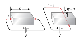
- Voltage (V) — the electrical pressure that pushes electrons through a circuit, measured in volts (V). Also called electromotive force (EMF).
- Current (I) — the flow of electric charge, measured in amperes (A). Think of current as the number of electrons passing a point per second.
- Resistance (R) — the opposition to current flow, measured in ohms (Ω). Every load (sensor, LED, buzzer) has resistance which determines how much current it draws.
Measuring voltage and handling voltage drop
- Use a digital multimeter to check the AUX voltage at the control panel and at the device. Measure under normal load for accurate results.
- Long cable runs introduce voltage drop. If the run is long or the device draws significant current, voltage at the far end can be lower than at the panel.
- Reduce voltage drop by using thicker wire (lower gauge), shorter runs, or local power sources.
Typical alarm system voltages
- Auxiliary (AUX) supply: commonly 12 V DC (nominal) for sensors and peripherals.
- Charging voltage: many control panels float batteries at around 13.5 V DC during charging.
Voltage regulators and power supplies keep these levels stable. Too low a voltage can cause malfunctions or false alarms; too high a voltage can damage components.
Practical tips for installers
- Measure at the device: Always measure voltage at the end device as well as at the panel.
- Check polarity: Most alarm devices are polarity-sensitive—reversed polarity can damage electronics.
- Use correct wire gauge: Match wire gauge to the expected current and run length; consult standard voltage-drop tables or calculators.
- Test under load: Batteries and power supplies can read fine without load but fail under load. Test with the system armed or with a test load.
- Protect circuits: Use fuses, proper connectors, and secure terminations to prevent faults.
Practical examples
- A sensor with low resistance draws more current from a 12 V supply.
- A long cable introduces resistance and lowers the current available to the device.
- A device with high resistance draws less current, even with the same voltage.
Simple circuit explanation
A complete circuit needs:
- A voltage source (for example, a battery or power supply)
- A conductor (wiring)
- A load (sensor, alarm, LED)
- A switch or control device to open and close the path

In alarm systems, the control panel provides the voltage, wires carry the current, and devices such as sensors and sounders provide resistance.
Common Mistakes Beginners Make
Confusing voltage and Current
Many beginners think voltage and current are the same. Voltage is pressure; current is flow. Both are needed for a circuit to work.
Misunderstanding load vs supply
Some installers think a device must always be supplied with the same voltage at any distance. In reality, the supply voltage may drop over long wire runs, and the load determines how much current is drawn.
Ignoring Voltage drop
Long cable runs and small wire sizes create voltage drop. This can cause a device to fail even if the panel voltage looks correct.
Overlooking polarity
Many alarm devices are polarity sensitive. Reversing the positive and negative wires can damage electronics.
Real-World Applications
Household wiring
Household wiring uses the same basic principles: voltage pushes current through wires, while resistance in appliances determines how much current flows. Get an Electrician for modification to any Household wiring. Household wiring is AC. Do not work or play with household wiring. Get a Professional.
Electronics
In electronics, resistors, sensors, and LEDs are designed with specific resistance values so they draw the correct current at a given voltage.
Batteries and chargers
Alarm systems often use 12 V DC batteries and charging supplies. The battery voltage must be kept within the correct range to avoid damage and ensure reliable operation.
Summary
- Voltage is the electrical pressure that pushes current.
- Current is the flow of charge through a circuit.
- Resistance is what limits that flow.
- Ohm’s law ties all three together: V = I * R.
- In alarm systems, proper voltage, correct wire gauge, and attention to voltage drop are critical for reliable performance.
Related articles
FAQ
Q: What voltage do alarm systems use?
Alarm systems typically use 12–13.5 V DC: ~12 V for AUX devices and ~13.5 V while charging backup batteries.
Q: Why is correct voltage important?
Incorrect voltage can cause false alarms, device reset/failure, or permanent damage. Maintain proper AUX voltage and check under load.
Q: How do I measure voltage in an alarm system?
Use a multimeter to measure AUX voltage at the control panel and at the device. Measure while the system is operating to account for voltage drop.
Q: What is voltage drop and why does it matter?
Voltage drop is the loss of voltage along a cable run due to wire resistance. Excessive drop can starve devices of the voltage they need to operate reliably.
Q: How can I reduce voltage drop?
Use thicker (lower AWG) wire, shorten cable runs, or provide local power near the device.